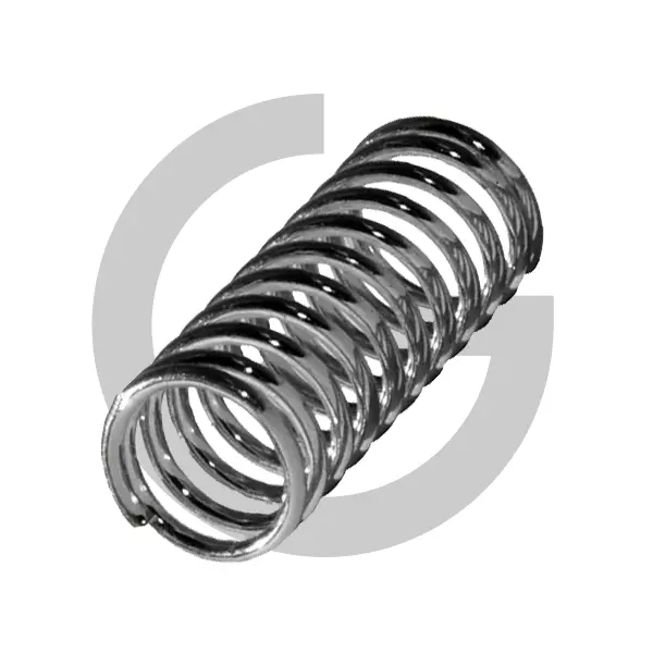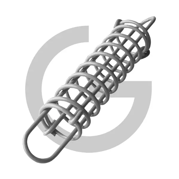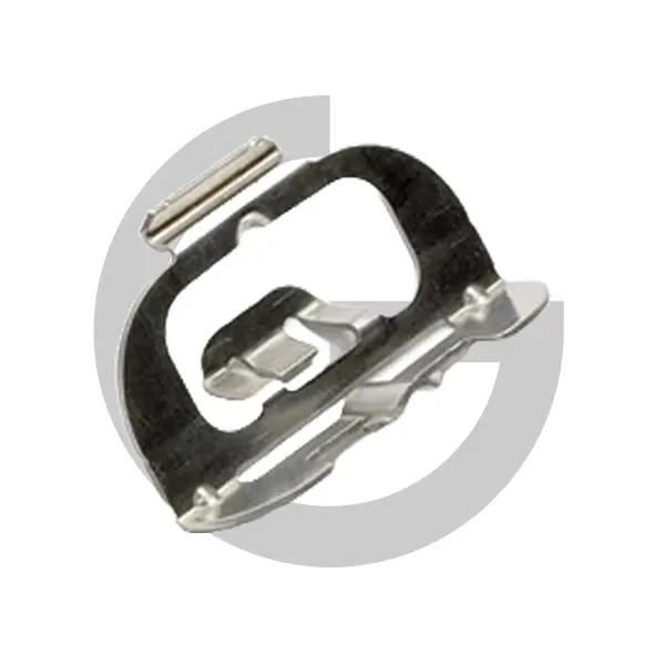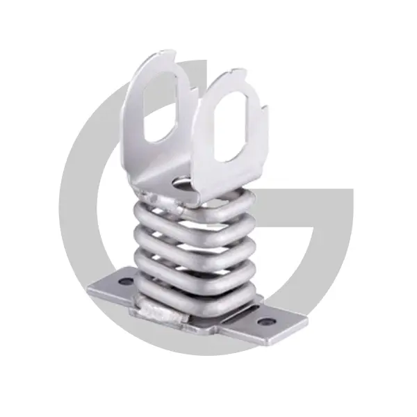
Every spring maker knows this drawing. It is dimensioned to perfection: 2.5 mm wire, 24 mm outside diameter, 60 mm free length, 8.5 active coils, every figure carrying a tight tolerance. Load is mentioned nowhere. No force at working height, no stroke, no cycle count, not a word about what the part has to do once fitted. It lands on quoting desks everywhere, Hagens’ desk in Støvring included, and it can be coiled exactly as drawn and still fail in the assembly within weeks, because a copied geometry says nothing about whether the design behind it was ever right. Most trouble with custom springs starts in that gap between what gets drawn and what gets needed.
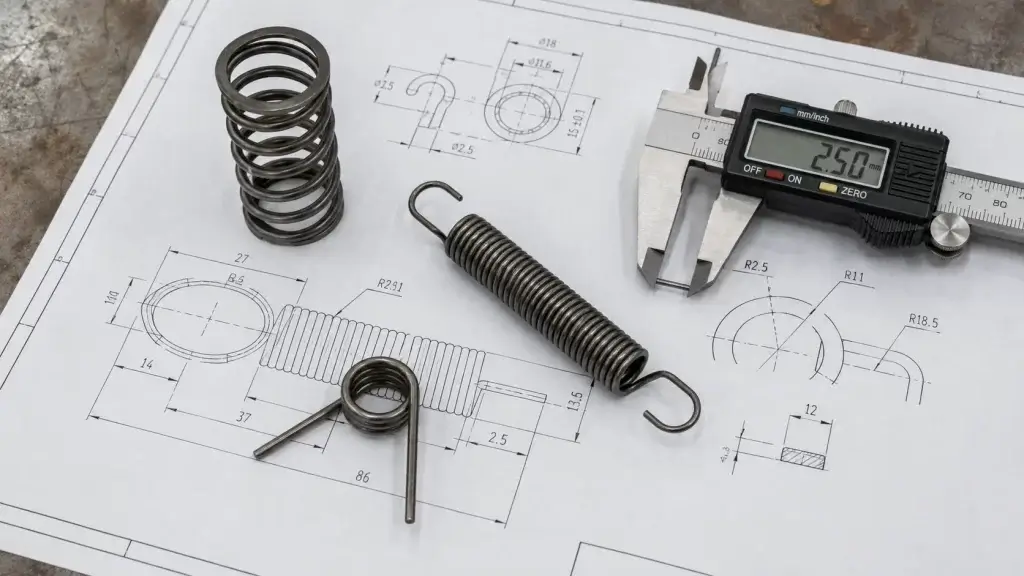
A spring is not really a shape. It is a function: a defined force at a defined length, repeated for a defined number of cycles in a defined environment. Geometry is one way of producing that function, and rarely the only way. Specify the function and your manufacturer can optimise wire, index and material around it. Specify only the shape, and every downstream decision is locked in before anyone has checked whether it works. Seven parameters carry the whole functional definition, and together they take up less space than most title blocks.
Why do fully dimensioned drawings still fail?
Because the numbers that get toleranced are not the numbers that matter. EN 15800, the quality standard for cold coiled compression springs, does not put a tolerance on wire diameter or coil count at all. It tolerances the coil diameter, the free length L0, perpendicularity and parallelism (e1 and e2), and above all the spring forces F1 and F2 at their working lengths. The standard treats force as the product characteristic and geometry as the means of getting there. A drawing that fixes every dimension but no force inverts that logic, and incoming inspection against it will happily pass springs that push too hard or too soft for the job.
In reality the failure mode is predictable. Small permitted deviations in coil diameter, free length and end grinding each sit inside their own tolerance band, and they stack. Two springs can both measure “to drawing” and still differ noticeably in force at working height, because nobody defined what that force should be. One check catches the stack-up: a measured force at a measured length. That single line is worth more than ten dimensional callouts, and it is the line most geometry-only drawings leave out.
The seven parameters, in the order they matter
What follows is the specification we wish every request carried. An engineer who answers these seven points has defined the spring completely, whether it ends up as a compression, tension or torsion design, and has left the manufacturer room to propose something better than the first sketch.
- Two load points. Force F1 at length L1 and force F2 at length L2. Two points fix the spring rate and the working window in a single line, and they are exactly the characteristics EN 15800 tolerances. If the application only has one defined load, give that one plus the stroke.
- The installation envelope. Bore diameter or rod diameter if the spring is guided, the maximum solid height the mechanism can absorb, and the length available at assembly. Envelope conflicts found at the quoting stage cost an email; found at the prototype stage they cost a design loop.
- Spring index. The ratio of mean coil diameter to wire diameter. EN 15800 accepts an index from 4 to 20, but 4 to 12 is the window where coiling behaves predictably: below 4 the wire fights the forming tools, above 12 the finished springs tangle in handling and transport. An envelope that forces the index outside that window deserves a conversation before it gets a price.
- Material grade. For unalloyed carbon wire, EN 10270-1 defines the grades SL, SM and SH for static duty and DM and DH for dynamic duty, each with a tensile band that depends on wire diameter. Grade DH spans 2230 to 2470 N/mm² at 1.00 mm wire and 2660 to 2940 N/mm² at 0.30 mm. Corrosive or medical environments move the choice to stainless grades under EN 10270-3, with full material traceability.
- Tolerance grade. EN 15800 offers grade 1, 2 and 3, where grade 1 is the tightest and grade 3 the widest. Grade 2 is the industry default. Order grade 1 only on the characteristics where precision earns its cost, not across the whole drawing.
- End configuration. Closed and ground ends or plain ends on compression designs, hook type and hook orientation on tension springs, leg length and leg angle on torsion designs. Tension designs add one figure of their own: the initial tension coiled into the body, which sets the force needed before the coils even separate.
- Environment and lifetime. Expected cycles to end of life, operating temperature, corrosion exposure and any required surface protection or shot peening. A spring cycling a million times a year is a different product from one holding a static preload, even when both carry the same loads.
What does a tighter tolerance grade actually buy?
Less than most drawings assume, and more than most budgets expect. Moving a characteristic from grade 2 to grade 1 under EN 15800 narrows its permitted band, and in practice the manufacturer pays for that with slower coiling, more frequent machine adjustment and tighter sorting, all of which lands in the piece price. That spend is justified where the spring meets a hard interface: a force window a valve must hit, a free length that sets an assembly gap, a diameter that decides whether the part slides freely in its bore.
Across the rest of the drawing it buys nothing the mechanism can feel, which is why the economical specification names one or two grade 1 characteristics and leaves the remainder at grade 2.
Know where cold coiling stops
Every process has an edge, and for cold coiling the edge sits around 16 mm wire according to the scope of EN 15800. Beyond that point, forming forces and residual stresses grow until hot coiling or a different construction takes over, and the cost curve bends sharply upward. In practice Hagens runs cold forming up to 18 mm wire for agricultural pick-up designs, which sits at the very heavy end of what the process allows.
The lesson for a specifier is short. State the loads and let the wire diameter fall out of the calculation. A wire forced one size up for comfort can cross that process line and double the piece price, not because the spring contains more steel, but because the part suddenly needs a different forming process.
Send the function, keep the drawing
The drawing from the opening usually gets an undramatic ending. Two questions go back: what force does the assembly need at working height, and how many cycles per year does it see? More often than not, the answers redefine the spring with one load point moved or one wire size smaller, inside the same bore, at a lower piece price than the drawn geometry would have cost. Nothing about the drawing was wrong. It was answering a question nobody had asked yet.
Keep sending the drawing; it carries the envelope better than words do. Just send the seven parameters with it, and the first prototype has a fair chance of being the last.