This is the single most common assembly failure with helical torsion springs, and it has nothing to do with the torque calculation. A torsion spring does not hold its shape while it works. Wind it in the direction it was built for and the body contracts in diameter and stretches in length, both by amounts you can calculate before anyone cuts metal. Three of the four failures we see on returned parts trace back to that movement being ignored: the spring binds on its support, it was wound against the load, or the leg was drawn longer than the body can carry. None of the three is a manufacturing defect, and all three are settled at the torsion spring design stage.
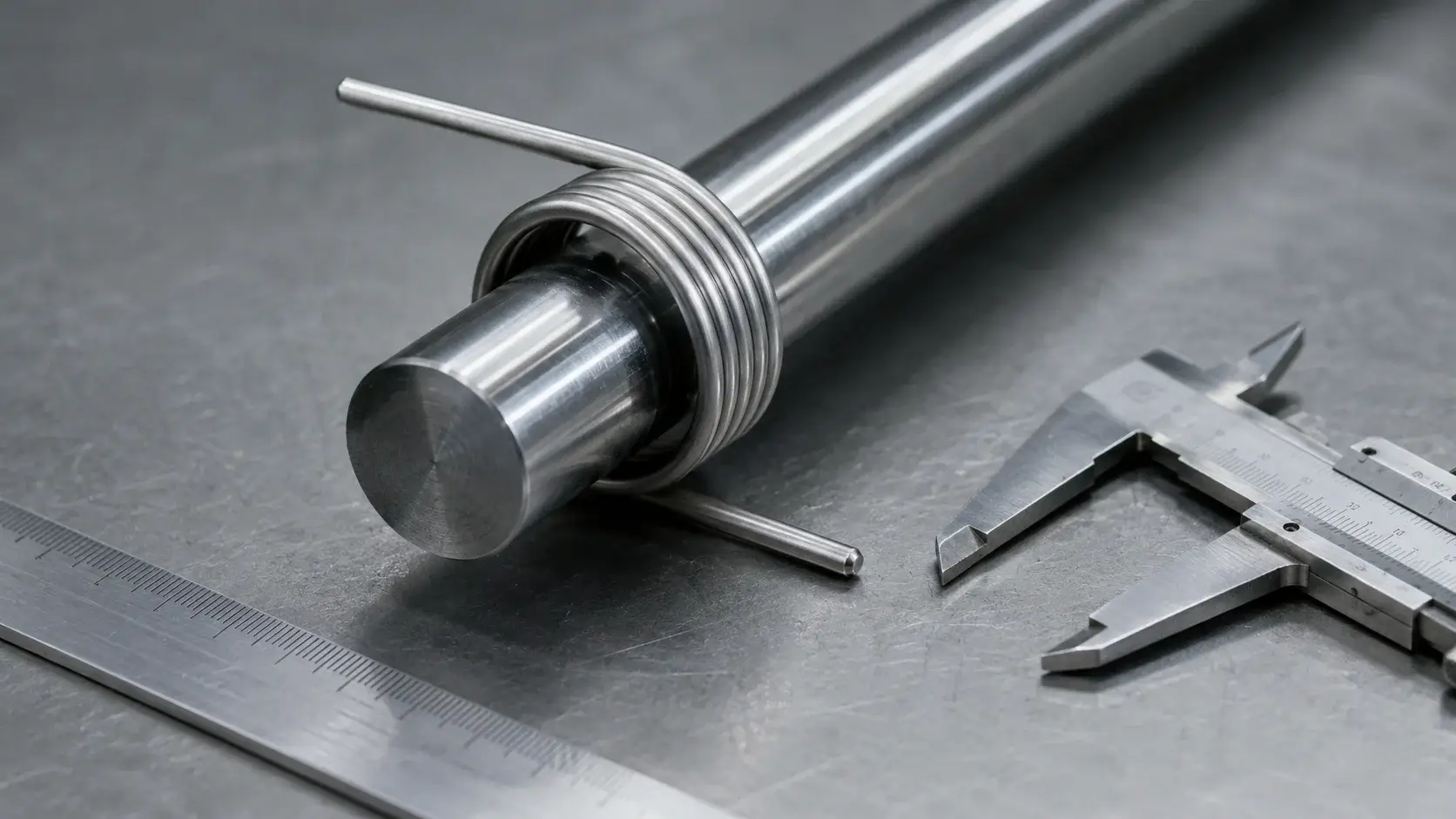
The inside diameter is a moving number
The number stamped on a drawing as the inside diameter is the free-state value, measured with no load on the legs. Under deflection it drops, and the relationship is straightforward: the loaded inside diameter equals N divided by the sum of N and REVs, multiplied by the free inside diameter, where N is the number of active coils and REVs is the number of leg revolutions. A ten-coil spring rotated through a quarter turn therefore sits at 10 divided by 10.25 of its free diameter, or a little over 97 percent of it. Rotate the same spring through a full turn and it drops to roughly 91 percent. On a 20 mm inside diameter that is a loss of nearly 2 mm of clearance, which is more than most designers leave in the first place.
Fewer coils make the effect sharper, not milder. A four-coil spring taken through a full revolution lands at 80 percent of its free inside diameter, so a nominal 20 mm bore closes to 16 mm while the assembly is doing exactly what it was designed to do. In practice the mistake is rarely arithmetic. It is that the shaft or mandrel gets dimensioned against the free diameter printed on the drawing, because that is the only diameter written anywhere.
Short springs are the dangerous ones. Fewer coils, more movement per revolution, less warning.
So size the support against the smallest diameter the spring will ever reach, not the largest. Take the inside diameter at full working deflection, and set the mandrel at about 90 percent of that figure. Whatever clearance remains covers manufacturing tolerance on both parts and leaves room for the coils to move without dragging. Going much below 90 percent is not a free safety margin either: an unsupported spring buckles sideways at large deflections, and a mandrel that is too slim stops holding it straight.
Body length grows as the spring winds down, by roughly one wire diameter for every full 360 degree revolution of the leg. On a short spring in a shallow pocket that is the difference between a part that turns freely and one that rubs against the housing face for its whole service life. Both movements come from the same rotation, so if you have calculated one you already have the input for the other.
Which way should the spring be wound?
A helical torsion spring is wound either right-hand or left-hand, and the two are not interchangeable parts with a cosmetic difference. Residual stresses left in the wire by the coiling operation are favourable in one direction and unfavourable in the other. Load the spring so the body contracts and those residual stresses work with you. Load it so the body opens up and they work against you, and the usable stress range drops well below what the calculation predicted.
Wind direction therefore has to be fixed by the assembly, not chosen by the manufacturer. Establish which way the arm rotates in service, then specify the wind that makes the body close during that rotation. A spring that opens under load will still function on a test bench and will still produce a torque reading close to the target. It fails early, in service, at a cycle count nobody predicted, and the fracture surface looks like ordinary fatigue rather than a specification error.
That last detail is what makes it expensive. The evidence points at the material, and the material was never the problem.
There is a second reason the direction matters, and it shows up in the same assemblies. A spring that opens under load grows in inside diameter instead of shrinking, which means the clearance calculation above runs the wrong way and the coils start to climb the shaft rather than settle on it. That failure presents as binding, exactly like an undersized mandrel, which sends the investigation to the wrong place.
Why does a long leg give you less force?
Legs are usually treated as the part of the spring that transmits load, and that is only half of what they do. Stress concentration at the bend where the leg leaves the body runs considerably higher than the calculated stress in the coils themselves, and how much higher depends on the bend radius. A tight radius at that transition is where a torsion spring cracks, not in the middle of the body where the coil stress is highest on paper.
Leg length changes the load path as well. The lever arm is the distance from the centre of the spring body to the point where force is applied on the leg, and the achievable force is the maximum moment divided by that arm. Move the contact point 50 percent further out and the force at that point drops by a third, from the same spring, with no change to the coil geometry. Engineers who need more force from a fixed envelope usually reach for thicker wire first, when shortening the arm would have delivered it without touching the spring at all.
Check that before the wire size changes. Moving a contact point is a drawing revision; a new wire diameter is a new tool.
Leg deflection scales the same way. The longer the leg and the further out the load is introduced, the more the leg itself bends before the coils have done anything, and that bending adds to the stress at the transition radius rather than relieving it. Long legs are sometimes the only option because of what the assembly looks like, and they are entirely manufacturable, but the transition radius and the wire then have to be chosen for them. That is where custom springs depart from a catalogue part: in torsion spring design the leg geometry drives the wire specification, not the other way around.
Check these four things before you machine the housing
Cylindrical helical torsion springs made from round wire with a linear characteristic are calculated to EN 13906-3, which covers both cold and hot coiled versions. That standard sets out the moment, the angular rate and the stress. What it will not do is tell you whether the pocket you have machined fits the spring at the end of its travel, because that depends on parts of the assembly the spring maker never sees. In reality four numbers close that gap, and they belong on the drawing alongside the torque:
- The inside diameter at maximum working deflection, not the free value, with the mandrel set near 90 percent of it.
- The body length at maximum deflection, allowing one wire diameter of growth per full leg revolution.
- The wind direction, stated as right-hand or left-hand and tied to the rotation the arm makes in service.
- The lever arm, given as the distance from the body centre to the actual contact point, not the overall leg length.
One more figure is worth carrying into the calculation. Loading to between 70 and 80 percent of the permissible bending stress is what buys a long fatigue life; run above the elastic limit and the spring takes a permanent set, losing torque quietly rather than breaking. A part that has relaxed still fits, still moves, and no longer does its job, which makes it harder to diagnose than a fracture.
Material choice, by contrast, is comparatively settled. Wire from ø0.2 mm to ø25.0 mm, round or square section, in EN 10270-1 cold drawn, EN 10270-2 oil hardened or EN 10270-3 stainless covers most industrial work, with Elgiloy, Hastelloy C-276 and Inconel X-750 available where temperature or corrosion rules the ordinary grades out. Picking the grade is rarely what decides whether the spring survives.
Go back to the hinge that seized two thirds of the way through its travel. The wire was right, the torque was right, and the spring met every dimension on the drawing. It closed to 16 mm around a 19 mm shaft because the shaft had been sized from a free-state number, and no calculation of moment would ever have caught it. The diameter under load, the length under load, the wind and the arm: get those four onto the drawing and the spring in the assembly behaves like the spring on the bench.